Horizontal Alignment
Understanding Horizontal Alignment. Road planning is divided into several stages. It begins with the horizontal alignment, continues with the longitudinal profile of the road, and ends with the cross…

Understanding Horizontal Alignment
Road planning is divided into several stages. It begins with the horizontal alignment, continues with the longitudinal profile of the road, and ends with the cross-sections. We start with the centerline of the road.
- Open a New Project in your CivilCAD software.
- In AutoCAD/ZWCAD, draw a 2D Polyline that will serve as the Horizontal Alignment of the road's centerline.
- From the main menu bar, go to Roads → Horizontal Alignment.
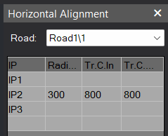
- This will open a window on your right. Click the arrow at the top-right corner of the table to select a road from your Roads List. You may switch to another road design by clicking on its designated row.
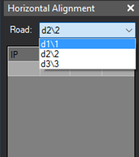
- Click on the row corresponding the road you wish to design.
- To define the centerline of the road: Choose ‘Select’ from the from the command box at the bottom of the table. In the AutoCAD/ZWCAD command line, press 'Enter' for <Polyline>. Move to the drawing area and choose the drawn Polyline and click ‘Enter’.
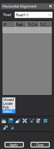
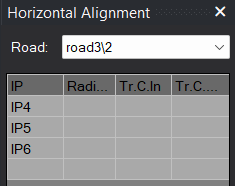
- At the right you will see a Panel Table with a List of IP's (Intersection Points).
- Press Apply And a window will appear on the drawing with the following options:
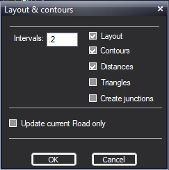
- Choose the 3 upper parameters. Press ok. Your road alignment will be on the screen you would also notice Post-Alignment Updates: at the DWG View - the Centerline turns red, Data blocks appear at the IP's, Sections are shown at defined intervals. At the Bottom un the Coordinates Table Displays - there are newly added points.
- Once the road has been added to your project, you may enter additional details in the table on the right, such as the radius of the turns and the length of the clothoids. After completion, press Apply and redo the previous stages. Note that tangent markers have been added to the curves.
Horizontal Alignment Setting
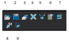
1. Read Center Line from file - Reading the center line data from LandXML File or Dis File.
2. Save to LandXML File - Saves the center line data to LandXML File or LandXML Surface.
3. Erase current IP - Stand on a row and press this button to erase an IP.
4. Clear all IP's - Deleting all center line data. A warning will appear before this function is activated.
5. Reorder all roads. This option is very useful when dealing with a project that includes multi roads, and whereas the numbering of the roads or IP's are not in order (for example, if we have deleted a certain road from the project and later add some new roads, the prefix of the IP's will not be following between the roads).
6. Options. Options button. Click on this button to open a new window. In this window you can determine the settings of your roads. Please see Horizontal Alignment Options
7. Reverse current ROAD. (Will change coordinates names and first section will be the last).
8. Pick station. (Will give the information about the picked dot).
9. Change alignment.
👌 Tips:
1. It is also possible to copy and paste a centerline from another drawing — select the line in the source drawing, press Copy, and then press Paste at the original coordinates in the CivilCAD project.
2. It is best practice to work after creating a surface and ensuring that breaklines are correctly assigned to maintain surface accuracy. Verify that the surface is generated and visible in the model space. Use the Surfaces chapter instructions: How to Create a Surface (Contours) - CivilCAD User Manual. And check roads list. Use roads list chapter instructions: Road List - CivilCAD User Manual.
How Did We Do?
Horizontal Alignment Options