Vertical Alignment
Understanding Vertictal Alignment. After defining the horizontal alignment of the road, we can proceed to define the longitudinal section. From the main menu bar, go to Roads → Vertical Alignment. Th…

Updated
by shlomit weller
Understanding Vertictal Alignment
After defining the horizontal alignment of the road, we can proceed to define the longitudinal section.
- From the main menu bar, go to Roads → Vertical Alignment.
- This will open a window on the right. Click the arrow at the top-right corner of the table to select the road from your Roads List. Press 'Apply'; a window will appear in the center of your screen. Press 'Apply' again. A section will apear on your screen.
- From the command window of AutoCAD/ZWCAD, select the 'Polyline' command and draw the desired profile. Press 'Enter' and then click 'Apply'. This will open a window in the center of your screen; click 'Apply' again. The section line will turn red, and information will appear on the table at the lower portion of your screen. You should add the radius of the curve un the 2T column and press 'Apply' again.
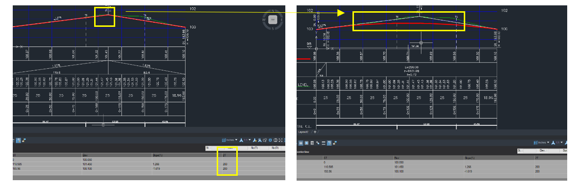
- The road’s longitudinal section will follow the curve you defined.
- You can adjust parameters in the road’s longitudinal profile either through the table or directly in the drawing. Please note that modifications can only be made in one of these interfaces during a single workflow. If changes are applied in both, the table values will take precedence over the drawing adjustments.
- When the road’s longitudinal section is complete, please close the window and return to the alignment view.
- Press 'Apply' here as well, so that the alignment and the longitudinal section are synchronized.
How Did We Do?
Vertical Alignment Options