Pipeline List- Steps. This guide covers the core workflow for designing gravity networks in CivilCAD Before designing a pipeline, you must have an active surface (DTM) to define your elevations. If y…
Updated
by Yael Zitvar
Pipeline List- Steps
This guide covers the core workflow for designing gravity networks in CivilCAD
Before designing a pipeline, you must have an active surface (DTM) to define your elevations.
Step 1: Create a Support Layer Create a new layer for your geometry. This keeps your design organized and prevents it from merging with other site data.
Action: Create a new layer in your CAD environment.
Sample File: You can use the pre-configured layer: CU-SSWR-SPRT.
Step 2: Plan Your Flow Direction You must identify the "Low Point" of your system before you draw a single line
Pro Tip: Work from Low to High Always start planning from the lowest elevation(the outlet) and work your way up to the highest point. This ensures you are designing with gravity flow in mind from the very beginning.
Use thePick Heighttool to click on the surface and see the exact elevation at any point.
Step 3: Draw the Pipeline Centerline Define the pipe's physical path using Polyline commands- Create segments according to your guidelines. Each vertex will become a manhole.
Use the Polyline commands (the same in your CAD environment) to draw the outline.
Pro Tip: Main Line FirstFocus on designing theMain Sewage Linebefore adding secondary lines/branches.
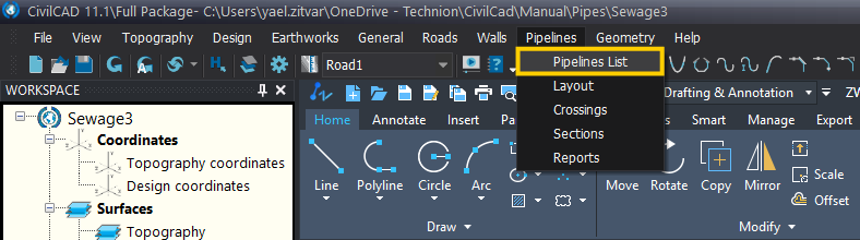
Step 4: Open the Pipelines List Go to the top menu, select Pipelines, and click Pipelines List.A new window will appear on the right side of your screen. This interface is where you define the identity of each pipe, including its name, type (e.g., Sewage), and profile shape (e.g., Round).
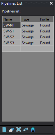
Step 5: Define Your Pipelines Click the first row and enter the names and types for the pipes you drew in the "SPRT layer".
Pipeline Name: Enter a unique ID for each line.
Type: Select the pipeline type from the dropdown (Sewage, Drainage, Water Supply, Cables).
PipelineProfile Shape: Choose the shape (e.g., Round).
Pro Tip: Use Naming Hierarchies Create meaningful names that reflect the pipe's purpose.
Sample File Example:SW-M1 (Sewage Main 1) or SW-S1 (Sewage Secondary 1).
Pipeline List Toolbar Overview
Add Line
Delete Line
Delete All
Find Lines
Unit control
Creates a new entry in the list
Removes the selected pipeline
Clears the entire list.
Search specific pipes in the project.
Use this to define units for Diameter,
Manhole, and Wall thickness.
Read more below.
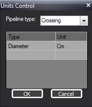
Understanding Units Control
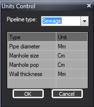
The Units Control settings allow you to define the measurement scales for your infrastructure components. Setting these correctly ensures that your pipeline data remains consistent across all reports and calculations.
You can set specific units for each element based on the Pipeline Type (e.g., Sewage, Water, Drainage, Cables).
Default Settings:
In most projects, sewage pipelines standard units are:
Pipe Diameter: Measured in mm (e.g., 600 mm).
Manhole Size/Pop: Measured in cm (e.g., 200 cm).
Wall Thickness: Measured in mm.
Always verify your units before entering data in the Layout window to avoid scaling errors in your 3D model.
The Unit Control window also controls the Crossings unit module. Make sure you choose the right units for your design
To continue creating a sewage pipeline using 'Pipeline Layout":