How to Use Pipeline Layout for Sewage. The Layout module is the bridge between your CAD geometry and CivilCAD's engineering database. This guide will walk you through linking your polylines to specif…
Updated
by Yael Zitvar
How to Use Pipeline Layout for Sewage
The Layout module is the bridge between your CAD geometry and CivilCAD's engineering database. This guide will walk you through linking your polylines to specific pipeline identities and configuring the visual parameters, such as diameters and labeling styles required for a professional site plan.
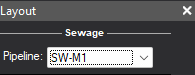
Step 1:Open Pipeline Layout Window Go to Pipelines -> Layout, and choose the line you want to define form the dropdown list.
Step 2: Convert Drawings to the Pipeline List Go to Pipelines -> Layout.
Click the Select button at the bottom
Click the corresponding Polyline in your drawing
Press Enter to confirm
This step converts your CAD geometry to the smart data you defined in the Pipelines List. Repeat this for every line in your project.
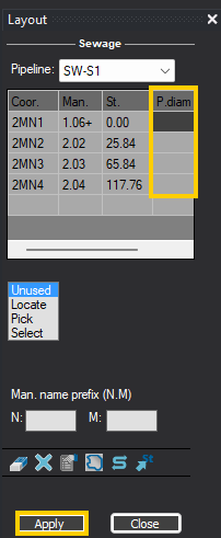
Step 3: Define Pipe and Manhole Diameters Enter the diameters for your pipes and manholes based on the units set in the Pipelines List in the Layout window table. Click Apply to save the changes.
Pipe Diameter: Enter the internal width of the pipe.
Manhole Diameter: Enter the size of the manhole structures at each vertex.
Sample File: Sets the main pipe diameter to 600 mm and the manhole diameter to 200 cm.
Pro Tip: Scroll to the right to adjust pipe and manhole diameter
Step 4: Refine the Layout Appearance Use the Layout toolbar to manage your geometry and labels.
Layout Toolbar Overview
Delete Manhole
Clear All
Options
Zoom to Pipeline
Reverse Direction
Pick Station
Removes a single specific manhole
Removes all manholes from the current pipeline
Adjusts display settings.
Read more below.
Automatically centers the screen on the selected pipeline.
Flips the start and end points of the pipe (useful if you drew it in the wrong flow direction).
Click any point on the line to see its exact distance (running station) from the start.
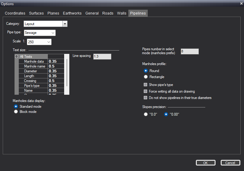
Pipeline Layout Options
The Options menu in the Layout window allows you to control the visual presentation of your pipeline and manhole data on the drawing. General Display Settings
Scale: Set the drawing scale (e.g., 1:250) to ensure labels and symbols appear at the correct size relative to your design.
Text Size: Customize the height of individual text parameters, such as Manhole name, Diameter, Length, and Crossing data, to maintain clarity.
Manhole Data Display You can choose how manhole information is presented on your plan:
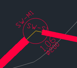
Standard Mode: Displays manhole data as simple, aligned text labels.
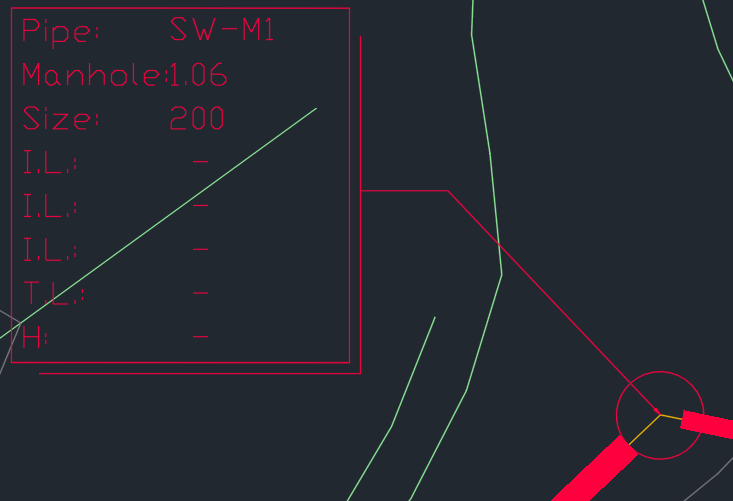
Block Mode: Uses a CAD block to contain the data for a more professional and organized look.
Adjustments: You can rotate the block angle for better placement.
Block Selection: Choose a specific block type based on the number of inputs/parameters you need to display.
Additional Controls
Manhole Profile: Toggle between Round or Rectangle shapes for the manhole symbols.
Slopes Precision: Define the decimal accuracy for slope labels (e.g., "0.0" or "0.00").