Pipeline Sections Options
Pipeline Sections Options. The Options menu under the Sections category allows you to establish design rules, constraints, and presentation styles for your vertical profiles. We will divide the optio…

Updated
by Yael Zitvar
Pipeline Sections Options
The Options menu under the Sections category allows you to establish design rules, constraints, and presentation styles for your vertical profiles. We will divide the options into 4 sections- see below:
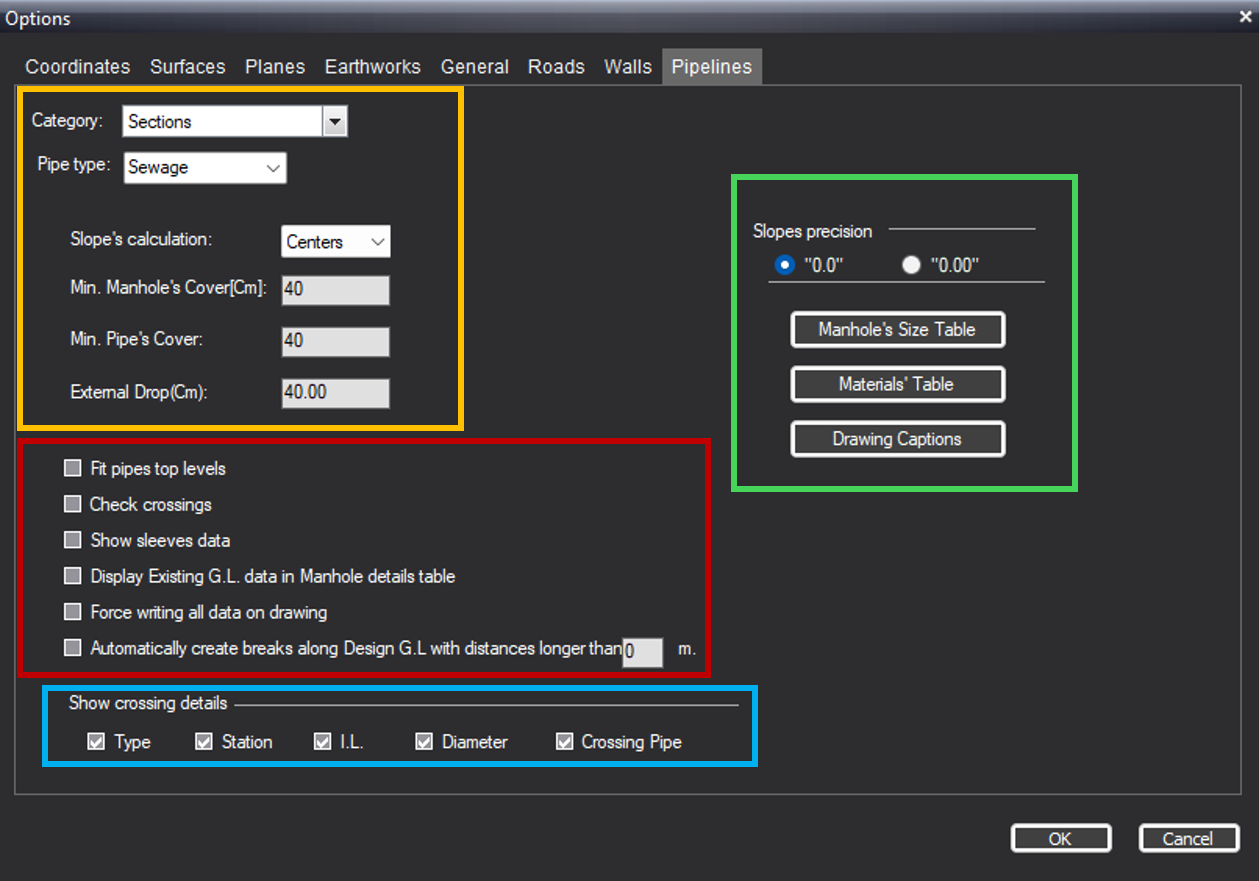
Design Rules & Constraints
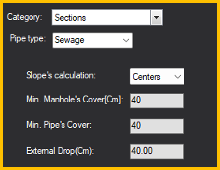
- Pipe Type: CivilCAD automatically detects and displays the current utility type you are designing (e.g., Sewage).
- Slope's Calculation: Choose whether hydraulic slopes are calculated between the Centers of the manholes or their inner Edges.
- Min. Manhole's Cover [Cm]: If the vertical distance from the bottom of the manhole to the ground level falls below this value (default is 40), the software pushes the manhole structure upward.Note: This constraint is less commonly utilized in standard workflows.
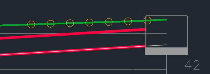
- Min. Pipe's Cover: Defines the minimum allowable clearance between the top of the pipe and the ground level. If your design violates this threshold, CivilCAD generates a visual alert on the section drawing (yellow circles).
- External Drop [Cm]: Sets the maximum allowable drop height between incoming and outgoing pipes at a manhole before CivilCAD creates a secondary, external drop pipe.
Automation & Display Toggles
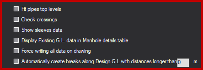
- Fit pipes top levels: When enabled, aligns the crown (top inner surface) of connecting pipes smoothly.
- Check crossings: Actively screens for utility clashes. If an intersection with another infrastructure line is detected, it prevents the collision by automatically adjusting the pipe's design height.
- Show sleeves data: Toggles the visibility of protective casing or sleeve heights in the section view.
- Display Existing G.L. data in Manhole details table: Includes the natural ground level elevations directly inside the lower manhole data band.
- Force writing all data on drawing: Overrides default spacing rules to force every piece of engineering text and label onto the final profile, preventing overlapping data from being hidden.
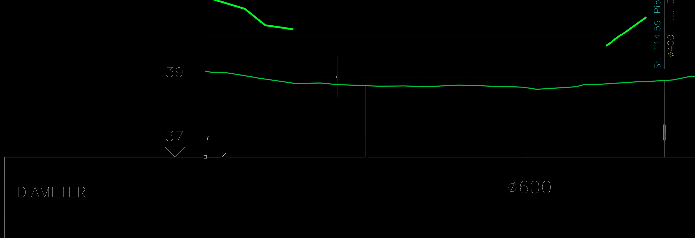
- Automatically create breaks along Design G.L. with distances longer than XXX m: Automatically separates ground elevation points if the designed surface contains data gaps longer than your specified threshold. see picture below of design G.L with breaks:
Show Crossing Details
Customize exactly which data is displayed on your section drawing for intersecting infrastructure by checking these boxes:
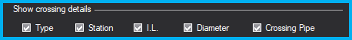
- Type (Utility type)
- Station (Running chainage)
- I.L. (Invert Level)
- Diameter
- Crossing Pipe
Advanced Settings & Tables
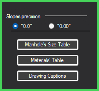
- Slopes precision: Define the decimal accuracy for slope callouts (e.g., single-decimal
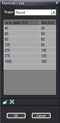
"0.0"or double-decimal"0.00"). - Manhole's Size Table: Opens a submenu for round and square shapes to map structural manhole diameters dynamically based on the total excavation depth.
- Materials' Table: Input and organize the piping materials available for your project. This data populates the drawing tables and filters directly into the final Bill of Quantities (BOQ).
- Drawing Captions: Customize the layout band table displayed below your vertical section. Use this interface to rename columns, add or delete fields, and adjust the vertical stacking order.
⚠️ Important: After modifying any parameters in this panel, you must click Apply to save your preferences and update your section views.
How Did We Do?
Creating Pipeline Sections
Moving a Manhole