Creating Pipeline Sections
New to this interface? For a complete breakdown of what every single column in this grid represents, read our dedicated article: Understanding the Manhole's Details Table Columns. Create Section Usin…

Updated
by Yael Zitvar
New to this interface? For a complete breakdown of what every single column in this grid represents, read our dedicated article: Understanding the Manhole's Details Table Columns.
Create Section Using the Manhole's Details Table
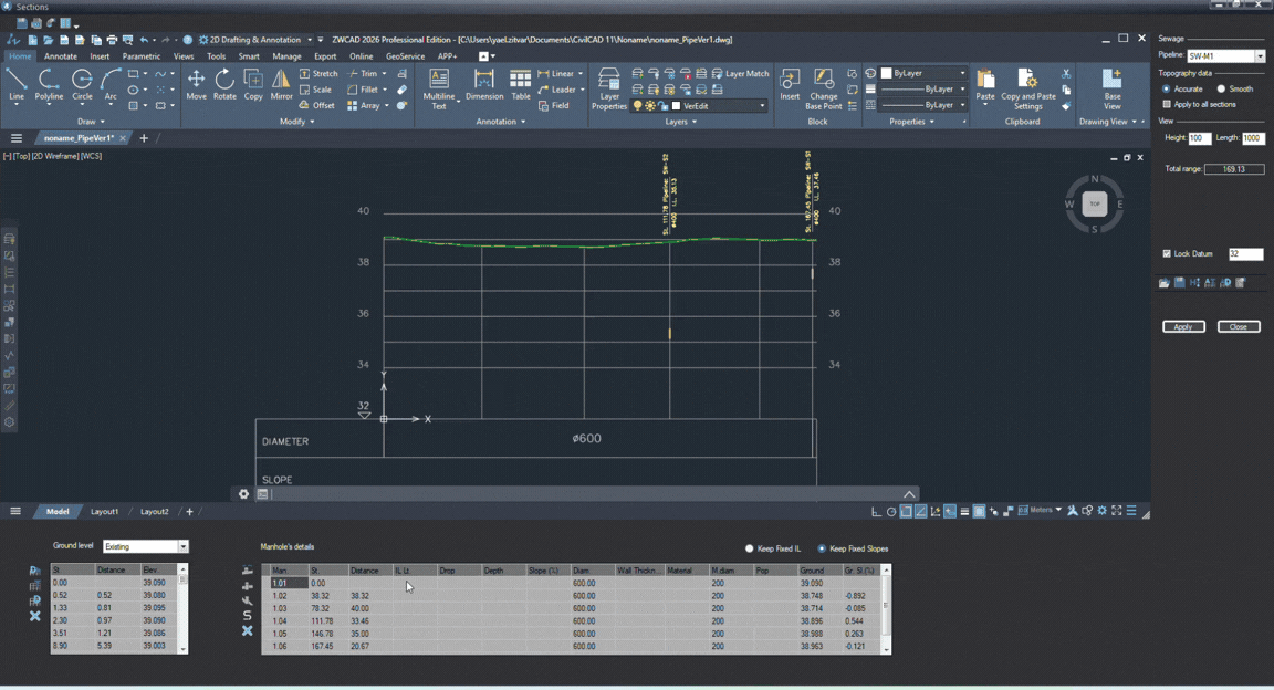
The Manhole's details table (located at the bottom right of the screen) is where you calculate and define your pipe's slopes, invert levels, and structural depths.
Design Warning: You can design your vertical profile either by typing values directly into this table or by manually shifting lines visually on the graphic profile sketch. Do not try to use both methods simultaneously; CivilCAD will continually overwrite one with the data from the other.
- Choose Your Design Constraint
Before entering any numeric data, in the top right corner of the panel. You must select how CivilCAD recalculates your pipe strings when an edit is made:- Keep Fixed IL: Locks the Invert Level elevations. If you alter the ground level or shift a manhole, CivilCAD keeps the pipe heights rigid and recalculates the hydraulic slopes to fit.
- Keep Fixed Slopes: Locks the Pipe Slopes (%). If you modify an invert level at one point, the software shifts adjacent elements up or down to keep your engineered slopes perfectly intact.
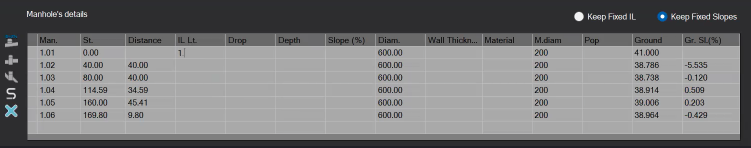
- Establish Your Starting Invert Level (Downstream Point)
Always try to begin your calculations from your outlet or lowest point in the system and work your way backward (upstream).- Locate your very first manhole (typically
1.01) in the table. - Click into the IL Lt. (Invert Level Left) column and type in your absolute design starting elevation. Press Enter.
- Locate your very first manhole (typically
- Define Your Pipe Gradients (Slopes)
With your baseline elevation established, you can now define how the pipes climb up the terrain.- If you selected Keep Fixed Slopes in Step 1, move down to the subsequent manhole rows and type your target gradients directly into the Slope (%) column.
- CivilCAD will automatically calculate all the matching intermediate IL Lt. and Depth values for you based on those percentages.
- Automate Structural Manhole Sizing
As your pipe levels change, the depth of your manholes changes with them according to data defined in the Manhole's Size Table see in Understanding Section Details Tables.- Click the Size Manholes button on the vertical toolbar directly to the left of the table.

- CivilCAD reads your new design depths and automatically resizes every manhole shaft diameter (M.diam) according to your project's predefined options.
- Click the Size Manholes button on the vertical toolbar directly to the left of the table.
- Calculate Vertical Drops
If incoming and outgoing pipes meet a manhole at significantly different heights due to steep terrain or size changes, you need to calculate internal drops.- Click the Calculate Drops button on the left toolbar.

- When the prompt appears, choose Yes to calculate drop steps across the entire line, or No to fill only the empty cells.
- CivilCAD will graphically create a small pipe diverging from the pipeline to the manhole in case there is a drop bigger than External Drop defined in Pipeline Sections Options.
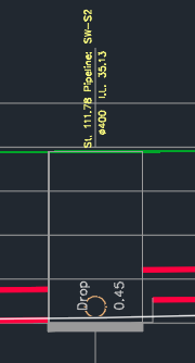
- Click the Calculate Drops button on the left toolbar.
- Step 6: Save and Render Your Profile
- Once all your slopes, levels, and sizes look correct in the table rows, click the Apply button on the right-hand panel.
- The database updates instantly, and your design levels will render completely onto the graphical section drawing.
Once you finish making visual adjustments in the drawing area, you must click Apply in the right-hand settings panel to save your geometric edits and update the database. - Adjust Your Design Dynamically
Engineering a profile is an iterative process. You can refine your network at any time by overriding any data cell directly within the grid.- Click into any editable column- such as Depth, Drop, Slope (%), or IL Lt.- and type your new design value.
- When you click Apply, CivilCAD will instantly recalculate the rest of the profile parameters automatically, strictly honoring the Design Constraint toggle (Fixed IL vs. Fixed Slopes) you selected in Step 1.
Design Geometrically in the CAD Window
Instead of using the table, you can design your vertical profile graphically by editing the drawing directly.
- Select the Correct Layer: Prerequisite. In the dedicated Sections CAD window, locate and select the VerEdit layer. This is the only active layer you can use to make graphical changes to the section.
- Move a Manhole Vertically: Select the profile line or the manhole structure, then use your standard CAD gripping tools to drag it up or down to adjust its level.
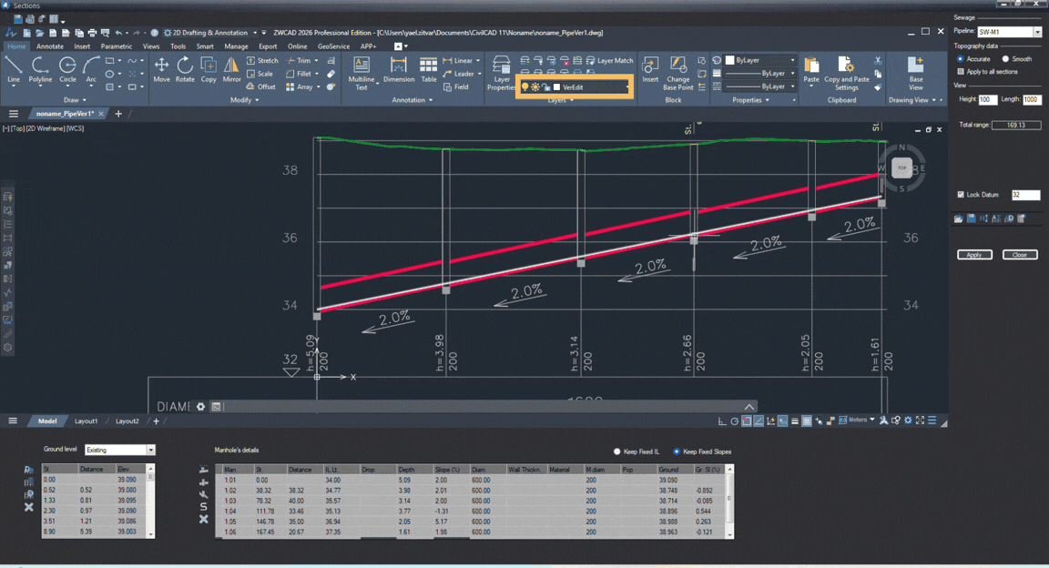
- Draw or Adjust Pipes:
- To draw: Connect your pipeline profile by drawing a straight line from one manhole to the next.
- To adjust: Click any existing pipe line and move it freely to change its slope or height.
- Save and Update: Click Apply in the right-hand panel to save your visual changes and update the profile data.
How Did We Do?
Intro to Pipeline Sections
Pipeline Sections Options