Managing Utility Crossings. The Crossings module ensures your pipeline design is safe from underground utility clashes. CivilCAD automatically identifies intersections between different pipelines wit…
Updated
by Yael Zitvar
Managing Utility Crossings
The Crossings module ensures your pipeline design is safe from underground utility clashes. CivilCAD automatically identifies intersections between different pipelines within your project and allows you to import external CAD data (like electricity, gas, or telecom lines) to map out full utility coordination.
Identify Crossings
CivilCAD uses two main visual indicators to tell you an intersection exists:
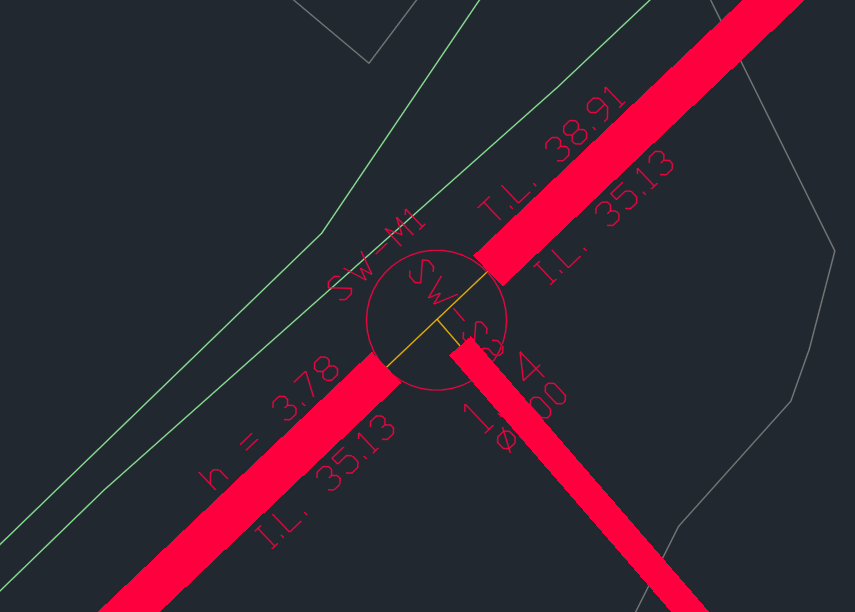
The Hierarchy Rule (Internal Pipes): When two pipelines designed inside CivilCAD cross each other, the manhole at the junction is named based on project hierarchy. The pipeline positioned higher up in the Pipelines List dictates the name of the shared manhole.
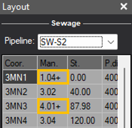
The Layout Indicator (+): Open your Layout window. If a manhole name has a plus symbol (+) next to it, CivilCAD has detected a utility crossing at that specific node.
Adding External Crossings
When an external engineer provides 2D or 3D utility data on a CAD layer, follow these steps to integrate it into your crossings-detection model:
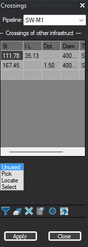
Open the Crossings Interface Go to the top menu, select Pipelines, and click Crossings. The table will immediately display all internal project crossings discovered automatically by CivilCAD.
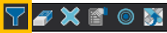
Filter and Select the External Utility Layer Click the Filter icon on the table toolbar. A new table will appear.Option A: Select the specific background CAD Layer and Entity type (e.g., Polyline, Line, Block) from the lists. Option B: Click the Select mouse icon -> go to the drawing -> select the crossing polylines directly from your drawing screen -> press Enter.
Step 3: Generate the Clash Points Click Apply. CivilCAD will instantly compute every physical intersection between your designed pipeline and the selected CAD entities, adding them as new rows in the Crossings table.
Step 4: Input Infrastructure Depths For each new external crossing point generated in the table, you must establish the elevation of the third-party infrastructure. Your workflow depends on the type of data provided by the external engineer:
If given 3D data: CivilCAD automatically extracts the correct elevation directly from the 3D entity geometry. Review the generated values in the table to confirm accuracy.
If given 2D data: The elevation column will be empty or set to zero. You must manually click into the cell and type the known absolute elevation or invert level (IL) for that specific crossing point.
Press Apply to see the intersection in the layout of the updated drawing
📌 When you open your Sections window. The new crossing points will automatically render onto your vertical profile drawings as crossing indicators, displaying critical vertical clearances.
Crossings Toolbar Reference
Use the toolbar of the Crossings window to manage your data:
Filter
Delete Crossing
Clear All Crossings
Options
Zoom to Crossing
Update Crossing
Select layers and object types to scan for external utility intersections.
Removes a single selected crossing point from the database.
Wipes all external crossing data from the active pipeline profile.
Configures the visual look of crossing labels on your plan drawing.
Instantly centers your CAD drawing view on the selected crossing point.
Critical Sync Tool: Resamples design paths and recalculates utility intersection locations if the horizontal route changes.