Understanding Section Details Tables
The Manhole's Details Table. When entering data, use this reference guide to understand what each column represents: Column Name. Description. Man. The Manhole ID number automatically assigned by Civ…

The Manhole's Details Table
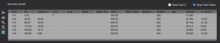
When entering data, use this reference guide to understand what each column represents:
Column Name | Description |
Man. | The Manhole ID number automatically assigned by CivilCAD based on your alignment hierarchy. |
St. | Station: The absolute running distance (chainage) from the starting node (0.00). |
Distance | The specific horizontal length between this manhole and the previous one. |
IL Lt. | Invert Level (Left): The absolute elevation of the bottom inside of the pipe where it meets the manhole structure. |
Drop | The vertical drop height inside the manhole when incoming and outgoing pipe levels differ. |
Depth | The vertical distance from the natural/design ground surface down to the pipe's Invert Level (IL). |
Slope (%) | The hydraulic slope gradient of the pipe segment. Entered as a percentage value. |
Diam. | The internal pipe diameter carried over directly from your Layout settings. |
Wall Thickness | The structural wall thickness of the pipe material. |
Material | Select the structural material designation for your billing records. |
M.diam | Manhole Diameter: The width of the manhole shaft. |
Pop | Structural parameters or pop-out dimension references if applicable. |
Ground | The ground elevation at this specific coordinate sampled from your active DTM. |
Gr. SL (%) | Ground Slope: The natural terrain grade percentage between the current and preceding station points. |
Table Design Toolbar
Use the 5 vertical control buttons located directly to the left of the data entry table to automate your vertical calculations and manage your profile structures.
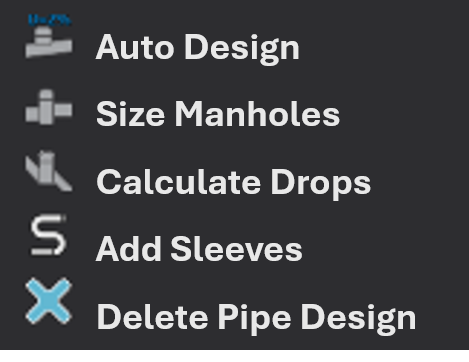
Design Toolbar Breakdown
- Auto Design: Automatically computes standard hydraulic slopes and invert levels across your network path based on the minimum cover depths defined in your project settings.
- Size Manholes: Automates structural configurations. Click this to instantly recalculate and match every manhole's diameter based on its total excavation depth, using the parameters you established in the Manhole's Size Table (Pipelines -> Sections -> Options).
- Calculate Drops: Automatically updates vertical step-downs inside your manholes to compensate for large diameters or steep pipe gradients.Pro Tip: When you click the Calculate Drops button, CivilCAD will prompt you with a dialog box:
- Select Yes to recalculate the drop heights across the entire pipeline.
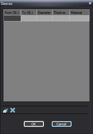
- Select No to calculate drops strictly for blank/empty cells, leaving your manual edits unchanged. - Add Sleeves: Reserved for custom structural utility overrides.
- Delete Pipe Design: Clears all of the manhole details table
Section Toolbar Commands
Use the bottom toolbar to manage your section files, refresh project data, and update design levels globally.

Section Toolbar Overview
Load Sections | Save Sections | Add dH to Ground | Get Topo Data (AT) | Get Design Data (AD) | Options |
 |  |  |  |  |  |
Imports external section layout data directly from a | Exports your current longitudinal section data to a text file for backup or external use | Global height adjustment tool. Use this to shift the vertical design lines up or down by a specified delta height (dH) across the entire profile | Samples the active drawing to fetch and refresh the latest topography levels along your pipeline route | Samples the project database to pull the latest infrastructure design edits made to your layout | Opens pop-up window for advanced configuration menu for sections (see Pipeline Sections Options article for more detail) |
Section Levels and Elevations
At the bottom-left corner of the Sections screen. This table displays the critical geometric data of your pipeline profile, organized by stationing, segment distances, and surface elevations.
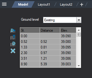
Ground Level Mode Selection
Use the Ground level dropdown menu above the table to switch between editing modes:
- Existing: Displays and isolates the existing natural terrain profile.
- Design: Allows you to view or manually input proposed design ground levels.
Table Overview
- St. (Station): The absolute running chainage along the pipeline (starting from 0.00).
- Distance: The incremental horizontal distance between two consecutive vertices or sampling points.
- Elev. (Elevation): The vertical height or level at that specific station point.
Data Control Buttons
 | Update Table / Design | Refreshes the active table column data with manual adjustments |
 | Get Topo Ground Level Data | Extracts and overwrites the elevation column with current data derived from your Existing DTM surface map |
 | Get Design Ground Level Data | Samples and loads current levels from your finished or active Design surface model |
 | Clear all Topography | Permanently removes the selected row or data entry vertex from the section path |
How Did We Do?
Moving a Manhole
Pipeline Crossing